Introduction to Guardian
Guardian is an automation platform based on python and EPICS. It was designed to meet the automation needs of the Advanced LIGO project, but it should have usage in any environment where state machine automation is relevant.
Overview
Guardian is designed as a hierarchical, distributed, state machine.
- Separate individual guardian processes (nodes) each oversee a particular domain of the overall system. These individual domains are known in guardian as systems. They are represented by the blue circles in Figure: Overview.
- Each system is described by a directed graph of states. Each state consists of code that describes a particular action on the domain, such as a change to the plant and/or verification of configuration. The states are joined together in a directed graph which describes the allowable transitions between states.
- The guardian node processes load their state graphs and execute the state code. Commands are issued in the form of state requests. The node then determines that path from the current state to the requested state from the state graph, and executes the states on the path in sequence.
- A hierarchy of nodes can be used to control a larger system. The low level nodes that talk to the plant itself are known as device nodes, and upper level nodes that control other lower level subordinate nodes are known as manager* nodes.
In Figure: Overview below, the dark blue manager nodes control other nodes, while the light blue device nodes at the bottom directly control the “front-end” hardware of the plant. This is not a strict distinction, as nodes can be mixed, talking both to the plant as well as directing other nodes.
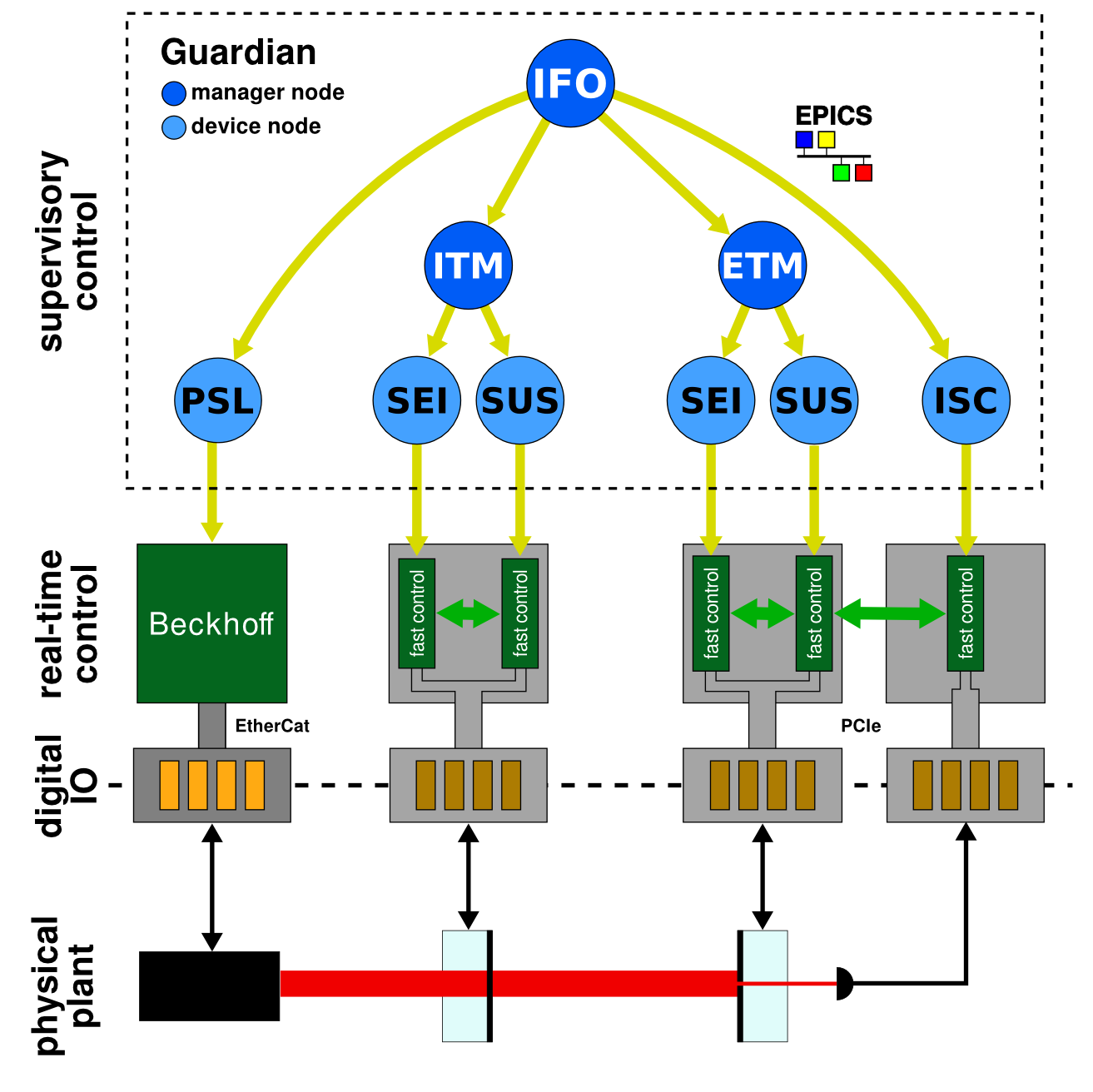
Figure: Overview
Each system is represented by a state graph. The state graph represents the full automation logic of the system.
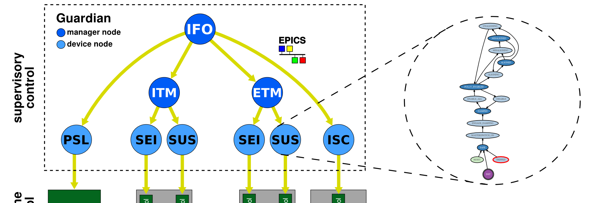
Figure: Overview - state graph
Guardian structure: state graphs
A guardian system (i.e. an individual node in Figure: Overview) is essentially a finite state machine description of the system to be controlled (which we will refer to as the “plant”). Each system consists of a set of Guardian States representing a block of automation logic. They are connected by directed edge definitions that represent the set of allowable transitions between states. This is all naturally described by a directed graph, where states of the system are graph nodes, and the allowable transitions are graph edges.
The state graph describes the dynamics of the system. The nodes in the graph represent the various states of the system, and the edges represent the allowable transitions between states.
States of the system (which are really just are represented as nodes in the graph, each consisting of executable code. Graph edges represent allowable transitions between states in the system. Edges have zero content, representing only which states are accessible from each other.
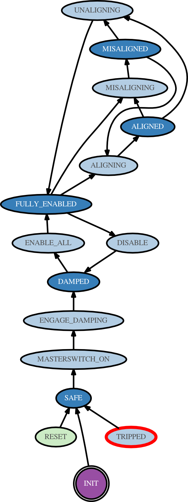
Figure: State graph
| [1] | Specifically a Moore finite-state machine, in that the action of the system is entirely a function of the state, and the edges have no content. |
Guardian behavior: graph traversal
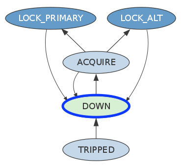
As mentioned above, guardian systems define state graphs that describe the dynamics of the system:
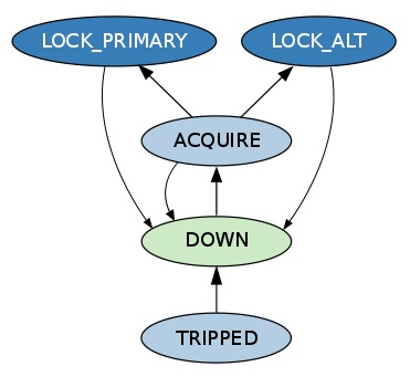
At any point in time, the system occupies a specific state in the graph. In the example below the current state is “DOWN” (blue outline):
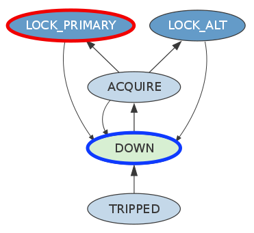
The system is directed in the form of a REQUEST state (“LOCK_PRIMARY” in thise case, red outline):
Once a REQUEST comes in, guardian calculates the shortest path (measured in number of hops) between the current state and the request. This is known as the path (green arrows and outlines):
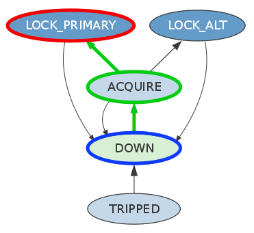
Guardian then begins executing all states in the path in sequence.
Each state is executed until it returns bool that evaluates
as True.
States can also return a str that is interpreted as the name
of a different state in the graph. In this case, guardian will
immediately jump to that state and start executing it. This is
known as a jump transition. Below, the “ACQUIRE” state returns the
string ‘TRIPPED’, which causes guardian to transition immediately to
the “TRIPPED” state (orange edge):
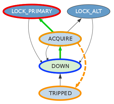
Jumps are ways for the system to bypass the basic dynamic constraints of the graph, and are intended for when the system under control is not behaving as expected.